Triangulating Images using Delauny Triangulation
Introduction
Late last year I created an small web application for triangulated images. The code is available on GitHub.
Image triangulation is a process which turns a standard image into a series of triangles. This creates a distinct artistic pattern where the image is made clearly of triangles.

The image triangulation web app uses a pipeline for creating these images. It's not just as simple as mapping triangles; there are multiple processing steps which this post will explain. I split this post into 3 key sections:
- Image Processing, where I explain the steps prior to splitting the images into triangles.
- Creating the triangulation, where I explain how we split the image into triangles using Delauny Triangulation.
- Colour Filling, where I explain how, after the previous two steps, we create the triangulated image.
The Pipeline
1. Image Processing
Blurring and Greyscaling
There are four steps in the pipeline that are performed prior to the Delauny Triangulation.
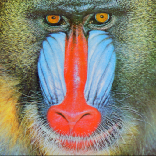
Let's say we take this image here as the input image:

First we blur the image using a Gaussian Blur on the input image. This reduces the noise in the image. Reducing the noise will assist us in edge detection later in the process, as we can more confidently that any large change in pixel compared to it's neighbours is valid and not the result of noise.
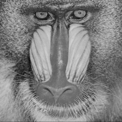
Once the image has been blurred, we then greyscale the image. This
process makes all pixels within the image take on the average value of
its RGB value. That is, for each pixel we perform the following:
pixel_value = (r + g + b) / 3.
Edge Detection
Once the image has been greyscaled we perform the interesting task of edge detection. Like the name suggests, this is where we process an image to show edges in the image. An edge is a set of connected pixels that lie on the boundary of two regions; if two regions of pixels have different values then an edge is the point at which those two regions meet.
There are many different functions for edge detection. To name a few there are the Prewitt Operator, Roberts Cross and Sobel Operator. This pipeline uses the Sobel Operator. The Sobel operator uses the following two masks.
Gx = [
    [-1, 0, 1],
    [-2, 0, 2],
    [-1, 0, 1]
]

Gy = [
    [-1, -2, -1]
    [0, 0, 0]
    [1, 2, 2]
]
Gx represents the mask for detecting vertical edges; Gy represents the mask for detecting horizontal edges. Each mask is applied to each pixel within the image and takes the absolute value for each pixel.
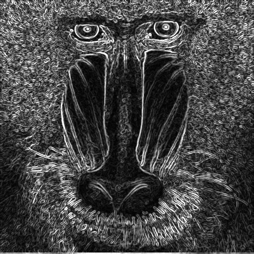
The sobel filter produces a monochrome image, where the black pixels
are not edges and the grey and white pixels are edge pixels. The
higher the value of the pixel, that is the more white the pixel is,
the larger the intensity of the edge. A pixel with the value of
RGB(30, 30, 30) will be a much less intense edge than
that with the value of RGB(256, 256, 256)
Then we move on to the final step of this pre-triangulation section: thresholding.
Thresholding
So far we have produced an image where we can see the edges. We want to turn this image into a series of individual points from which we can construct triangles. We don't want every edge pixel to be considered a vertex of a triangle because then there would be so many triangles we wouldn't be able to see them. Therefore, we want to fitler out the less intense edges. To do this, we use a thresholding algorithm.
Thresholding is simply where we set a threshold value, T, and if a pixel value falls below T then we remove that pixel from the image.
I won't go too in-depth on different thresholding algorithms as it is a whole topic in and of itself. Many different thresholding algorithms exist, such as using a global threshold, Otsu's algorithm and Niblack's. One issue with a global threshold is that lighting can change through the image meaning a set threshold value may not be appropriate for all of the image. For our task of triangulting images, we do not want to use a global threshold; the algorithm selected for thresholding for this specific pipeline is Niblack's, which uses an adaptive local threshold.
For each pixel, we calculate the threshold, T, using the following:
T = m + (k * s)
Where: m is the local mean pixel intensity over some neighbourhood n; k is a user defined parameter; s is the local standard deviation of pixel intensities over over n.
We scan each pixel using the equation and if the pixel falls below the
value of T then the pixel is removed from the image; those
that remain within the image are set to the value
RGB(0,0,0).
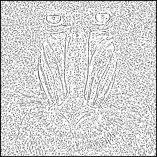
Once this thresholding has been applied to all pixels within the image we are left with a mostly white image with a set of black pixels. These will be used as the verticies for our triangles when we create the Delauny Triangulation.
2. Triangulation
In the previous section we created a thresholded image. It is a series of black pixels representing intense edges. We now move on to creating a triangulation, more specifically a Delauny Triangulation, from these black pixels. These pixels should now be viewed as points on grid, where each pixel has cartesian coordinates.
A Delauny Triangulation is a type of triangulation where the circumcircle of one triangle intersects with all vertices of that triangle but also intersects with no other triangle's verticies in the set of triangles that form the triangulation. A circumcircle is a circle that passes through all three vertices of a triangle.
There are many algorithms for constructing a Delaunay Triangulation. We will be using the Bower-Watson algorithm.
Bowyer-Watson
For this usage of the Bowyer-Watson algorithm, we take the set of black pixels as the input for the triangultion. This will act as a list of verticies, but begins in the algorithm as a list of points.
The first step of the Bowyer-Watson algorithm is to construct a "super-triangle", which is a triangle that encompasses the whole area of our points. In our pipeline we do this by creating a triangle using the following function:
const createSupertriangle = (vertices: Vertex[]): Triangle => {
    let minX = 0
    let maxX = 0
    let minY = 0
    let maxY = 0

    vertices.forEach((vertex) => {
        minX = vertex.x < minX ? vertex.x : minX
        maxX = vertex.x > maxX ? vertex.x : maxX
        minY = vertex.y < minY ? vertex.y : minY
        maxY = vertex.y > maxY ? vertex.y : maxY
    })

    const supertriangle = new Triangle(
        { x: -maxX * 10, y: -maxY * 10 },
        { x: (maxX * 10 + -maxX * 10) / 2, y: maxY * 10 },
        { x: maxX * 10, y: -maxY * 10 }
    )

    return supertriangle
}
Once we have created the super-triangle, we run the following algorithm, written in pseudocode, for each point:
    triangulation = [supertriangle]
    FOR EACH point IN pointsList:
        SET badTriangles = []
        FOR EACH triangle IN triangulation:
            IF point lies within circumcircle of triangle:
                SET triangleAlreadyInSet = False
                FOR EACH badTriangle IN badTriangles:
                    IF badTriangle equals triangle
                        SET triangleAlreadyInSet = true
                IF triangleAlreadyInSet IS False:
                    APPEND triangle TO badTriangles
        SET polygon = []
        FOR EACH badTriangle IN badTriangles:
            FOR EACH edge IN badTriangle:
                IF edge NOT part of another triangle in badTriangle:
                    APPEND edge TO polygon
        REMOVE badTriangles FROM triangulation
        SET newTriangle = Construct triangle from polygon
        APPEND newTriangle TO triangulation
    FOR EACH trinagle IN trianguilation:
        IF triangle shares vertex with supertriangle:
            Remove triangle from triangulation
We begin with the triangulation containing only the supertriangle and we pass in a list of points. For our purposes this list of points is the list of the black pixel's coordinates from our image.
We then create a list of "badTriangles", which are triangles that do not fulfill our criteria of having it's circumcircle contain only its vertices. For each new point we check all previous triangles in our trianglation to see if the addition of a new point breaks the criteria. Each new addition means that a triangle that previously fulfilled the critera of having a circumcircle intersect with only its own verticies may no longer fulfill this criteria. We add these triangles to the badTriangles list.
For each edge in each badTriangle in the badTriangles list we check if that edge is shared with the edge of another badTriangle. If it is not we add that edge to our polygon variable.
Once we have processed each of the badTriangles we remove them from the badTriangles list. We then form a new triangle from the polygon variable.
After each point in our point list has been processed we remove any triangles that share a vertex with the supertriangle we created at the start of the algorithm.
We now have a Delauny Trianglulation. In our use case, we have created a Delauny Triangulation from the pixels that survived our thresholding.
3. Adding Colour
We have taken an image and converted it into a Delauny Trianglation, created from thresholded pixels on the edges of regions within the image. We now approach our final task in the process, adding colour to the image Delauny Triangulation.
This is the simplest step of the process, but it can take a long time to run.
For each triangle in the triangulation we created we scan the original image and determine which pixels lie within the triangle. Each pixel is then associated with a triangle within the triangulation.
For each triangle we calculate the mean value of R, G and B for each pixel within the triangle. This will give us the average colour of all pixels within the triangle.
Once this is calculated we change the value of each pixel within the triangle to be the average value.
Once this has been done for all pixels, we will have a triangulated image.
Conclusion
In this post I have ran through the process I use in my web app to triangulate images. The code is available on GitHub, where you will also find instructions on how to run the app.
The process for creating a triangulation image can be summarised as follows:
-
Image Processing:
- Blur the image to remove noise
- Greyscale the image to reduce complexity of edge detection algorithms.
- Perform edge detection using a Sobel Filter.
- Threshold the image using Niblack's algorithm.
- Create delauny triangulation using the Bowyer-Watson algorithm.
- Fill in the colours by calculating the average pixel value for each pixel within each triangle.
Sobel Filter, Niblack's Algorithm and Bowyer-Watson's Algorithm are used in this triangulation pipeline. These are not the only algorithms that may be used for this task. For example, Sobel could be swapped out with other edge detection algorithms. As we know, each algorithm will have its own advantages and disadavantages.
I hope now that you have read this post it is clear to you how you can take an image and triangulate it.